
I’ve ventured back into the VXLAN / EVPN world this time within CML. In this lab i’ve used eBGP in the underlay.
I’m testing this to see the benefits of a single routing process in VXLAN fabrics.
I like to look at the reduction of protocols and inevitably simplification that allows for automation. (Although arguably some of the eBGP L2VPN EVPN configuration isn’t simple, but we’ll get to that).
Underlay Design
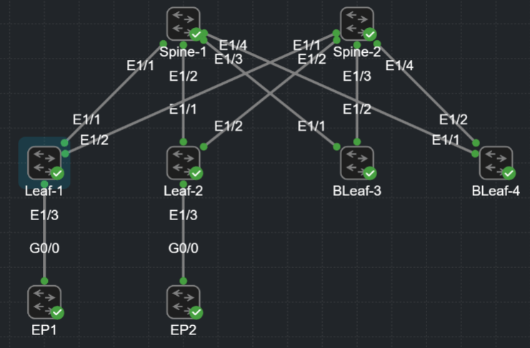
Here’s my topology, two spines four leaf and two endpoints.
I will be eBGP peering directly connected IPv4 over /31 point-to-point links. Note, we’re using eBGP so no route-reflection configuration is required.
I’ll then be using eBGP multihop to peer L2VPN EVPN with my Loopback100 interfaces.
To add, i’ll be using 8-byte ASNs. We’re using a multi-as design. Spine-1 and Spine-2 are using the same ASN. All the leaf nodes are different ASNs.
Spine-1 | Spine-2 : 65100.1
Leaf-1 : 65200.1
Leaf-2 : 65200.2
Leaf-3 : 65200.3
Leaf-4 : 65200.4
I’ll be adding some external connectivity in future pages, however no VPCs or shared VTEPs are required here. (See my VXLAN / EVPN – ISIS pages which show the required configuration for shared VTEPs).
eBGP Underlay – Physical Configuration
To start with i’ve configured my point to point interfaces and loopbacks. It’s very important we differentiate throughout this configuration which aspects are underlay and which are overlay.
My physical interface configuration is my underlay. The advertising of my loopback100 ip adress 10.255.255.1/32 is part of my underlay. However, the 10.255.255.1/32 IP address is leveraged by the overlay to build out my L2VPN EVPN peering.
#LEAF-1
interface Ethernet1/1
  description Link to SP1
  no switchport
  mtu 9216
  medium p2p
  no ip redirects
  ip address 192.168.1.1/31
  no ipv6 redirects
  no shutdown
!
interface loopback100
  description L2VPN-PEERING
  ip address 10.255.255.1/32
The Spine is the same configuration throughout
#SPINE-1
interface Ethernet1/1
  description Link to LF1
  no switchport
  mtu 9216
  medium p2p
  no ip redirects
  ip address 192.168.1.0/31
  no ipv6 redirects
  no shutdown
!
interface loopback100
  description L2EVPN-PEERING
  ip address 10.1.1.1/32
eBGP Underlay – eBGP Configuration
Now we’ve configured our base underlay configuration, we need to advertise the loopback100 address. Instead of using ISIS or OSPF we’re using eBGP so we can reduce the number of different processes we need to run. Plus there’s less to think about if we automate this configuration.
To start with I have configured the ipv4 address-family within my bgp ASN. The network statement is advertising the configured loopback100 address only. The loopback100 is the only IP we need to advertise for the underlay.
Also see maximum-paths 2. As we’re dual connecting our Leafs to the Spines we’ll receive two routes to every leaf loopback in our BGP RIB. One route via Spine-1 and another via Spine-2. Maximum-paths 2 installs 2 active paths into our routing table. (There’s an example of this in the confirmation section).
#LEAF-1
router bgp 65200.1
  router-id 10.255.255.1
  log-neighbor-changes
  address-family ipv4 unicast
    network 10.255.255.1/32
    maximum-paths 2
*Note the only difference on the Spine is we don’t use maximum-paths configuration.
Next we can configure our templates. Again this simplifies the configuration and can help with automation. Specifically updates to our BGP configuration in future.
Below we can see peer-policy UNDERLAY-POLICY. This only contains soft-reconfiguration inbound, but it gives the option to update every peer with configuration in future.
Next is the eBGP-SESSION peer-session template. I use this as my base session configuration. This is a good way of assigning bfd and password to every peer that is configured.
You can also nest this base session in another session template. We’ll see an example of this later when we want to apply our L2VPN configuration in conjunction with our base session configuration.
#LEAF-1
router bgp 65200.1
  template peer-policy UNDERLAY-POLICY
    soft-reconfiguration inbound
  template peer-session eBGP-SESSION
    bfd
    password thisisntmypassword
Now we can configure our underlay neighbors and apply our peer-policy and peer-session. Note these neighbors are configured for address-family ipv4 unicast ONLY!
#LEAF-1
router bgp 65200.1
  neighbor 192.168.1.0
    inherit peer-session eBGP-SESSION
    remote-as 65100.1
    address-family ipv4 unicast
      inherit peer-policy UNDERLAY-POLICY 1
  neighbor 192.168.1.3
    inherit peer-session eBGP-SESSION
    remote-as 65100.1
    address-family ipv4 unicast
      inherit peer-policy UNDERLAY-POLICY 1
A reminder that the distinction between eBGP underlay (IPv4) and overlay (L2VPN EVPN) is one of the main complexities of this configuration.
eBGP Underlay – Confirmation
Now finally we can confirm our configuration. First we can check our neighbors from our Leaf-1 to Spines are established as below. We can see 4 prefixes are received.
LEAF-1# sh ip bgp summ
BGP summary information for VRF default, address family IPv4 Unicast
BGP router identifier 10.255.255.1, local AS number 4272947201
BGP table version is 198, IPv4 Unicast config peers 2, capable peers 2
6 network entries and 9 paths using 2088 bytes of memory
BGP attribute entries [5/1840], BGP AS path entries [4/36]
BGP community entries [0/0], BGP clusterlist entries [0/0]

Neighbor        V    AS    MsgRcvd    MsgSent   TblVer  InQ OutQ Up/Down  State/PfxRcd
192.168.1.0     4 4266393601
                              1077        976      198    0    0 11:44:00 4
192.168.1.3     4 4266393601
                              1095        989      198    0    0 11:47:01 4
So lets check our prefixes in the BGP RIB are correct. We should see a loopback for every Spine and Leaf device in our fabric.
Note each of the loopback IPs received has two Next Hops (maximum-paths 2) apart from our spines.
LEAF-1# sh ip bgp
BGP routing table information for VRF default, address family IPv4 Unicast
BGP table version is 198, Local Router ID is 10.255.255.1
Status: s-suppressed, x-deleted, S-stale, d-dampened, h-history, *-valid, >-best
Path type: i-internal, e-external, c-confed, l-local, a-aggregate, r-redist, I-injected
Origin codes: i - IGP, e - EGP, ? - incomplete, | - multipath, & - backup, 2 - best2

   Network            Next Hop            Metric     LocPrf     Weight Path
*>e10.1.1.1/32        192.168.1.0                                    0 4266393601 i
*>e10.2.2.2/32        192.168.1.3                                    0 4266393601 i
*>l10.255.255.1/32    0.0.0.0                           100      32768 i
*|e10.255.255.2/32    192.168.1.0                                    0 4266393601 4272947202 i
*>e                   192.168.1.3                                    0 4266393601 4272947202 i
*|e10.255.255.3/32    192.168.1.0                                    0 4266393601 4272947203 i
*>e                   192.168.1.3                                    0 4266393601 4272947203 i
*|e10.255.255.4/32    192.168.1.0                                    0 4266393601 4272947204 i
*>e                   192.168.1.3                                    0 4266393601 4272947204 i
Finally, lets check our routing table and confirm the correct routes have been installed. Same as the BGP RIB we can see routes for all our spine and leaf device loopbacks. Spines have one next hop, the leafs have two next-hops utilising maximum-paths 2.
LEAF-1# show ip route bgp
IP Route Table for VRF "default"
'*' denotes best ucast next-hop
'**' denotes best mcast next-hop
'[x/y]' denotes [preference/metric]
'%<string>' in via output denotes VRF <string>

10.1.1.1/32, ubest/mbest: 1/0
    *via 192.168.1.0, [20/0], 11:52:08, bgp-65200.1, external, tag 4266393601
10.2.2.2/32, ubest/mbest: 1/0
    *via 192.168.1.3, [20/0], 11:55:08, bgp-65200.1, external, tag 4266393601
10.255.255.2/32, ubest/mbest: 2/0
    *via 192.168.1.0, [20/0], 11:52:08, bgp-65200.1, external, tag 4266393601
    *via 192.168.1.3, [20/0], 11:55:08, bgp-65200.1, external, tag 4266393601
10.255.255.3/32, ubest/mbest: 2/0
    *via 192.168.1.0, [20/0], 11:52:08, bgp-65200.1, external, tag 4266393601
    *via 192.168.1.3, [20/0], 11:55:08, bgp-65200.1, external, tag 4266393601
10.255.255.4/32, ubest/mbest: 2/0
    *via 192.168.1.0, [20/0], 11:52:08, bgp-65200.1, external, tag 4266393601
    *via 192.168.1.3, [20/0], 11:55:08, bgp-65200.1, external, tag 4266393601
Now we can ping between leaf node loopbacks for that fuzzy feeling. *Remember to source your address from your loopback100*
LEAF-1# ping 10.255.255.2 source 10.255.255.1
PING 10.255.255.2 (10.255.255.2) from 10.255.255.1: 56 data bytes
64 bytes from 10.255.255.2: icmp_seq=0 ttl=253 time=9.97 ms
64 bytes from 10.255.255.2: icmp_seq=1 ttl=253 time=13.444 ms
64 bytes from 10.255.255.2: icmp_seq=2 ttl=253 time=6.883 ms
64 bytes from 10.255.255.2: icmp_seq=3 ttl=253 time=3.111 ms
64 bytes from 10.255.255.2: icmp_seq=4 ttl=253 time=3.743 ms

--- 10.255.255.2 ping statistics ---
5 packets transmitted, 5 packets received, 0.00% packet loss
round-trip min/avg/max = 3.111/7.43/13.444 ms
LEAF-1#
I’ve also added a traceroute so we can see the first hop via the spine
LEAF-1# traceroute 10.255.255.2 source 10.255.255.1
traceroute to 10.255.255.2 (10.255.255.2) from 10.255.255.1 (10.255.255.1), 30 hops max, 48 byte packets
 1  192.168.1.3 (192.168.1.3)  2.99 ms  2.463 ms  1.426 ms
 2  10.255.255.2 (10.255.255.2) (AS 4272947202)  3.815 ms  4.083 ms  4.357 ms
And that’s our underlay. Next is our L2VPN EVPN overlay control plane followed by our VXLAN data plane.
