
Finally, i’ve taken the plunge again and configured some VXLAN. The plan is to achieve this configuration with as minimal effort as possible with as little commands, i’ve chosen an ISIS underlay this time however in future i’ll look to eBGP.
So why VXLAN and why EVPN? VXLAN is used to extend our layer-2 domain over layer-3 circuits. It is highly scalable, it can utilise features like anycast gateways and scan span across multiple pods and sites. VXLAN is the data plane. EVPN on the other hand is the control plane, EVPN advertises routes that allow VXLAN tunnels to establish and add additional features such as EVPN route-types which enable anycast gateways.
EVPN and VXLAN work great together however they are not a requirement of each other.
When scaling out our topology we add more Spines to increase the backplane or we increase the number of leafs to increase our capacity.
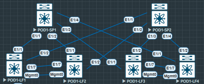
Here’s my starting point, EVE-NG N9Kv, two Spines, four Leaf. Single Pod. Leaf nodes are VPC connected to two Layer-3 switches.
(I did try this in CML but I had too many issues with N9000v and interface modules disappearing I gave up and came back to old faithful).
ISIS Underlay
To start with in any spine and leaf topology we must configure an underlay. This allows us to advertise our addressing, mainly loopbacks across our topology to allow our overlay control plane MP-BGP EVPN to peer and share routing information.
First we enable our feature and configure our ISIS instance, adequately named UNDERLAY, starting with our leaf nodes.
Some points: We’re using area 0010 and system.id 0001. System.id is unique and references the node for example: LF4 = 0004, LF1 = 0001. The same occurs for Spines but the system.id moves. Is-type level-2 is our backbone level, and there’s no requirement for anything else (level-1 = stub).
It’s also worth mentioning the loopback addressing for Leaf is 10.222.222.X where X = Leaf Number. The Spine loopback address are 10.111.111.X where X = Spine Number.
RFC 1195 – ISIS
#POD1-LF1
feature isis
!
router isis UNDERLAY
  net 49.0010.0000.0000.0001.00
  is-type level-2
  log-adjacency-changes
  address-family ipv4 unicast
#POD1-SP1
feature isis
!
router isis UNDERLAY
net 49.0010.0000.0001.0000.00
is-type level-2
log-adjacency-changes
address-family ipv4 unicastNext we configure our interfaces to allow ISIS to form adjacencies. Here we utilise ip unnumbered to ensure ISIS forms adjacencies via its loopback IP. The ip unnumbered loopback0 command negates the need to configure point-to-point /30 or /31 addresses everywhere in our network.
It’s worth noting the medium p2p command ensures the connection is treated as a point-to-point connection. This is required to enable ISIS over unnumbered interfaces.
Secondly the use of no isis hello-padding always is used to reduce unnecessary buffers / headers, and can be used when interface MTUs are matching. In reality I only used this because my adjacencies were stuck in INIT state and this was the fix. (If you’re using MPLS with ISIS I wouldn’t do this).
The ip router isis UNDERLAY finishes off the interface configuration, allowing the UNDERLAY ISIS instance to initiate adjacencies.
IS-IS Hello Padding Behavior – Cisco
#POD1-LF1
interface loopback0
  description UNDERLAY
  ip address 10.222.222.1/32
  ip router isis UNDERLAY
!
interface Ethernet1/1
  description Link to SP1
  no switchport
  mtu 9216
  medium p2p
  ip unnumbered loopback0
  no isis hello-padding always
  ip router isis UNDERLAY
  no shutdown

interface Ethernet1/2
  description Link to SP2
  no switchport
  mtu 9216
  medium p2p
  ip unnumbered loopback0
  no isis hello-padding always
  ip router isis UNDERLAY
  no shutdown
#POD1-SP1
interface loopback0
description UNDERLAY
ip address 10.111.111.1/32
ip router isis UNDERLAY
!
interface Ethernet1/1
description Link to LF1
no switchport
mtu 9216
medium p2p
ip unnumbered loopback0
no isis hello-padding always
ip router isis UNDERLAY
no shutdownNow the UNDERLAY is configured we can confirm it’s useable. We should see ISIS adjacencies with loopbacks available in route tables.
POD1-SP1# sh isis adj
IS-IS process: UNDERLAY VRF: default
IS-IS adjacency database:
Legend: '!': No AF level connectivity in given topology
System ID       SNPA            Level  State  Hold Time  Interface
POD1-LF1        N/A             2      UP     00:00:26   Ethernet1/1
POD1-LF2        N/A             2      UP     00:00:24   Ethernet1/2
POD1-LF3        N/A             2      UP     00:00:31   Ethernet1/3
POD1-LF4        N/A             2      UP     00:00:22   Ethernet1/4
Here we can see level2 adjacencies are UP and all the /32 loopbacks for each of the Leaf and Spines are available, as always we can confirm this with a ping.
POD1-LF1# sh ip route
IP Route Table for VRF "default"
'*' denotes best ucast next-hop
'**' denotes best mcast next-hop
'[x/y]' denotes [preference/metric]
'%<string>' in via output denotes VRF <string>

10.111.111.1/32, ubest/mbest: 1/0
    *via 10.111.111.1, Eth1/1, [115/41], 00:48:05, isis-UNDERLAY, L2
10.111.111.2/32, ubest/mbest: 1/0
    *via 10.111.111.2, Eth1/2, [115/41], 00:00:37, isis-UNDERLAY, L2
10.222.222.1/32, ubest/mbest: 2/0, attached
    *via 10.222.222.1, Lo0, [0/0], 00:57:36, local
    *via 10.222.222.1, Lo0, [0/0], 00:57:36, direct
10.222.222.2/32, ubest/mbest: 2/0
    *via 10.111.111.1, Eth1/1, [115/81], 00:47:59, isis-UNDERLAY, L2
    *via 10.111.111.2, Eth1/2, [115/81], 00:48:18, isis-UNDERLAY, L2
10.222.222.3/32, ubest/mbest: 2/0
    *via 10.111.111.1, Eth1/1, [115/81], 00:47:57, isis-UNDERLAY, L2
    *via 10.111.111.2, Eth1/2, [115/81], 00:48:18, isis-UNDERLAY, L2
10.222.222.4/32, ubest/mbest: 2/0
    *via 10.111.111.1, Eth1/1, [115/81], 00:47:58, isis-UNDERLAY, L2
    *via 10.111.111.2, Eth1/2, [115/81], 00:48:18, isis-UNDERLAY, L2
Now we’ve confirmed the UNDERLAY is routable by pinging each Leafs loopback we can begin to configure our BGP EVPN control plane and VXLAN overlay…
POD1-LF1# ping 10.222.222.2
PING 10.222.222.2 (10.222.222.2): 56 data bytes
64 bytes from 10.222.222.2: icmp_seq=0 ttl=253 time=12.558 ms
64 bytes from 10.222.222.2: icmp_seq=1 ttl=253 time=8.465 ms
64 bytes from 10.222.222.2: icmp_seq=2 ttl=253 time=8.872 ms
64 bytes from 10.222.222.2: icmp_seq=3 ttl=253 time=6.002 ms
64 bytes from 10.222.222.2: icmp_seq=4 ttl=253 time=4.319 ms
^C
--- 10.222.222.2 ping statistics ---
5 packets transmitted, 5 packets received, 0.00% packet loss
round-trip min/avg/max = 4.319/8.043/12.558 ms
POD1-LF1# ping 10.222.222.3
PING 10.222.222.3 (10.222.222.3): 56 data bytes
64 bytes from 10.222.222.3: icmp_seq=0 ttl=253 time=48.636 ms
64 bytes from 10.222.222.3: icmp_seq=1 ttl=253 time=11.277 ms
64 bytes from 10.222.222.3: icmp_seq=2 ttl=253 time=10.72 ms
64 bytes from 10.222.222.3: icmp_seq=3 ttl=253 time=5.774 ms
64 bytes from 10.222.222.3: icmp_seq=4 ttl=253 time=5.465 ms
^C^[[A
--- 10.222.222.3 ping statistics ---
5 packets transmitted, 5 packets received, 0.00% packet loss
round-trip min/avg/max = 5.465/16.374/48.636 ms
POD1-LF1# ping 10.222.222.4
PING 10.222.222.4 (10.222.222.4): 56 data bytes
64 bytes from 10.222.222.4: icmp_seq=0 ttl=253 time=8.116 ms
64 bytes from 10.222.222.4: icmp_seq=1 ttl=253 time=3.884 ms
64 bytes from 10.222.222.4: icmp_seq=2 ttl=253 time=3.716 ms
64 bytes from 10.222.222.4: icmp_seq=3 ttl=253 time=6.053 ms
64 bytes from 10.222.222.4: icmp_seq=4 ttl=253 time=4.057 ms
^C
--- 10.222.222.4 ping statistics ---
5 packets transmitted, 5 packets received, 0.00% packet loss
round-trip min/avg/max = 3.716/5.165/8.116 ms
POD1-LF1# 
Leave a comment