
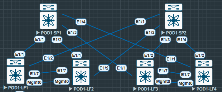
As before we’re using the same topology and configuration. To ensure efficient traffic forwarding within our VXLAN fabric we can utilise multicast in the underlay, it’s not a requirement but this ensures our BUM traffic is forwarded efficiently (Broadcast Unknown Multicast).
There are two main options for multicast in the underlay in regards to VXLAN:
Option One: We map our VNIs 1:1 with unique multicast groups.
(Very efficient harder to manage).
Option Two: We use the same multicast group across all of our VNIs (Somewhat efficient and easier to manage).
In this lab i’ll be using option one and mapping different multicast-groups to each of the VNIs. For now we’ll concentrate on the multicast configuration, when we tie it all together with VXLAN we’ll see the 1:1 mapping of VNI to multicast group.
It’s also worth noting we’ll be utilising PIM-SM and an anycast RP. I have tested this with Bidir Phantom RP however it is more complicated with little benefit. Standard anycast RP seems easier and that’s what i’ve seen in the wild. The only DC use i’ve seen for Bidir Phantom RP is in inter-pod VXLAN networks. (Such as ACI Multi-Pod IPNs).
I have a write up on the ACI IPN Bidir Phantom RP from my time with my friends at Starfish – CISCO ACI IPN WHITEPAPER – Starfish VLABS
Multicast Underlay Configuration – Leaf
First as always we enable the required features.
#POD1-LF1
POD1-LF1# sh run | i feature
feature pim
Next we enable PIM-SM on all of our interfaces including (Including our loopback that is used for VTEP, we’ll cover this in our VXLAN configuration section).
#POD1-LF1
interface Ethernet1/1
  ip pim sparse-mode

interface Ethernet1/2
  ip pim sparse-mode
We must also configure the RP addressing and multicast groups. Note we only have one RP address, this is configured as anycast across both spines, there is no mention of anycast on the Leaf nodes in regards to multicast.
#POD1-LF1
ip pim rp-address 172.17.16.1 group-list 228.0.0.0/24 bidir
ip pim rp-address 172.17.16.1 group-list 229.0.0.0/24 bidir
Multicast Underlay Configuration – Spine
Next we configure the Spines again enabling the PIM feature, configuring all of our interfaces with pim sparse-mode however in addition to this we configure the anycast RPs. Note the RP address is the same configured on new Loopback1 on Spine1 and Spine2.
#POD1-SP1
interface loopback1
  description *** Anycast RP ***
  ip address 172.17.16.1/32
  ip router isis UNDERLAY
!
ip pim anycast-rp 172.17.16.1 10.111.111.1
ip pim anycast-rp 172.17.16.1 10.111.111.2
!
interface Ethernet1/1
  ip pim sparse-mode

interface Ethernet1/2
  ip pim sparse-mode

interface Ethernet1/3
  ip pim sparse-mode

interface Ethernet1/4
  ip pim sparse-mode
Multicast Underlay Confirmation
Now we can confirm that the configuration we have in place is actually working.
First we confirm our PIM-SM neighbors are UP.
POD1-LF1# sh ip pim neighbor
PIM Neighbor Status for VRF "default"
Neighbor        Interface            Uptime    Expires   DR       Bidir-  BFD
 ECMP Redirect
                                                         Priority Capable State
    Capable
10.111.111.1    Ethernet1/1          01:58:55  00:01:34  1        yes     n/a
  no
10.111.111.2    Ethernet1/2          01:59:14  00:01:24  1        yes     n/a
  no
POD1-SP1# sh ip pim neigh
PIM Neighbor Status for VRF "default"
Neighbor Interface Uptime Expires DR Bidir- BFD
ECMP Redirect
Priority Capable State
Capable
10.222.222.1 Ethernet1/1 01:59:34 00:01:25 1 yes n/a
no
10.222.222.2 Ethernet1/2 01:59:34 00:01:19 1 yes n/a
no
10.222.222.3 Ethernet1/3 01:59:33 00:01:32 1 yes n/a
no
10.222.222.4 Ethernet1/4 01:59:33 00:01:18 1 yes n/a
noNext we can confirm the anycast RP is available.
POD1-LF1# show ip pim rp
PIM RP Status Information for VRF "default"
BSR disabled
Auto-RP disabled
BSR RP Candidate policy: None
BSR RP policy: None
Auto-RP Announce policy: None
Auto-RP Discovery policy: None

RP: 172.17.16.1, (1),
 uptime: 02:09:36   priority: 255,
 RP-source: (local),
 group ranges:
 229.0.0.0/24  (bidir)
 228.0.0.0/24  (bidir)
We can also check the ip route to the RP address, here we see two routes to the same IP are available and listed as best next-hop
POD1-LF1# sh ip route 172.17.16.1
IP Route Table for VRF "default"
'*' denotes best ucast next-hop
'**' denotes best mcast next-hop
'[x/y]' denotes [preference/metric]
'%<string>' in via output denotes VRF <string>

172.17.16.1/32, ubest/mbest: 2/0
    *via 10.111.111.1, Eth1/1, [115/41], 02:00:53, isis-UNDERLAY, L2
    *via 10.111.111.2, Eth1/2, [115/41], 02:01:06, isis-UNDERLAY, L2
We can also check mroutes to confirm the multicast groups are available. Later on when the configuration is completed we’ll review these mroutes and identify the S,G for the VTEP.
POD1-LF1# show ip mroute
IP Multicast Routing Table for VRF "default"

(*, 228.0.0.0/24), bidir, uptime: 02:12:13, pim ip
  Incoming interface: Ethernet1/2, RPF nbr: 10.111.111.2
  Outgoing interface list: (count: 1)
    Ethernet1/2, uptime: 02:02:54, pim, (RPF)
On the Spines we see a different perspective for the anycast RP
POD1-SP1# sh ip pim rp
PIM RP Status Information for VRF "default"
BSR disabled
Auto-RP disabled
BSR RP Candidate policy: None
BSR RP policy: None
Auto-RP Announce policy: None
Auto-RP Discovery policy: None

Anycast-RP 172.17.16.1 members:
  10.111.111.1*  10.111.111.2

RP: 172.17.16.1, (1),
 uptime: 02:01:21   priority: 255,
 RP-source: (local),
 group ranges:
 229.0.0.0/24  (bidir)
 228.0.0.0/24  (bidir)
 224.0.0.0/9  (bidir)
Next we can move onto our Control Plane and then finally the VXLAN overlay.
