
Now we can finish up our VXLAN / EVPN fabric by configuring our VXLAN overlay. Again we’re using the same topology and configuration as already discussed through the “Single-Pod VXLAN / EVPN” series of posts.
VXLAN Feature Configuration
As always, we start by enabling the appropriate features. Below i’ll explain some of these features as they aren’t as self explanatory as ISIS or BGP.
feature nv overlay: Enables VXLAN functionality on NXOS such as VTEPs.
feature fabric forwarding: Enables anycast gateways, integration into firewalls and load-balancers with service-redirection.
feature interface-vlan: Enables the use of SVIs
feature vn-segment-vlan-based: Enables the mapping of VLANs to VXLANs.
Note: on our Spines we haven’t enabled feature interface-vlan as we aren’t using SVIs here.
POD1-LF1#
feature fabric forwarding
feature interface-vlan
feature vn-segment-vlan-based
feature nv overlay
Next on both the Leaf and Spines we need to configure nv overlay evpn, this enables the evpn control plane.
POD1-LF1#
nv overlay evpn
NVE / VTEP Interface Configuration
Now the required features are enabled and the evpn control plane is configured we can configure our NVE interface and shared VTEP. We’re utilising a shared VTEP as our Leaf nodes are configured as VPCs. The NVE is a logical interface that encapsulates and decapsulates VXLAN packets.
It is worth noting that any configuration across a VPC pair for VXLAN needs to be identical. *Its important not to shutdown the NVE interface, this will cause VPC inconsistencies and will result in VPC failover.
To start with we’ll configure a new Loopback interface, this will be our shared VTEP. This loopback address is advertised into our ISIS Underlay and PIM-SM is enabled.
To enable a shared VTEP we must use a secondary address. This secondary address acts as the shared VTEP address. We can see the primary loopback addresses across both Leaf switches within our VPC pair are unique, however the secondary is the same.
#POD1-LF1
interface loopback100
  description SHARED-VTEP
  ip address 100.200.255.3/32
  ip address 100.200.255.1/32 secondary
  ip router isis UNDERLAY
  ip pim sparse-mode

#POD1-LF2
interface loopback100
  description SHARED-VTEP
  ip address 100.200.255.2/32
  ip address 100.200.255.1/32 secondary
  ip router isis UNDERLAY
  ip pim sparse-mode
Now our shared VTEP interface is configured we can build out our NVE and ensure that the Shared VTEP Loopback100 is the source of the NVE.
Next we ensure host-reachability is utilising the BGP protocol as mechanism to learn and advertise host MAC address (L2VPN EVPN).
The virtual-rmac enables the advertisement of the VPC virtual MAC address. This stops packet loss in VXLAN / EVPN environments configured in conjunction with VPC (Specifically using MP-BGP L2VPN EVPN).
#POD1-LF1
interface nve1
  no shutdown
  host-reachability protocol bgp
  advertise virtual-rmac
  source-interface loopback100

#POD2-LF2
interface nve1
  no shutdown
  host-reachability protocol bgp
  advertise virtual-rmac
  source-interface loopback100
It’s also worth mentioning at this point the advertise-pip command. This works in conjuction with the virtual-rmac command and ensures the primary IP on loopback 100 is utilised for BGP next-hop when advertising prefix routes or leaf generated routes when VPC is enabled. Commands are as follows, only required on the leaf.
#POD1-LF1
router bgp 65001
  address-family l2vpn evpn
    advertise-pip
VXLAN L2VNI Configuration
Now the required NVE interface is configured we can implement our L2VNIs. In our design we are creating two L2VNIs. We have two Layer-3 switches connected on VPCs as endpoints for testing.
First we configure our VLAN and associate the vn-segment, again this is only configured on the Leaf nodes. Note the VNI range is from 4096 to 16,777,215. it’s always best practice to make our L2VNIs and L3VNIs wildly different numbers, this aids in troubleshooting. I always ensure part of the L2VNI vn-segement ID is the same as the VLAN ID.
#POD1-LF1
vlan 100
  vn-segment 160100
vlan 200
  vn-segment 160200
Next we can configure gateway addresses for the L2VNIs. This is done like any other SVI, however we configure fabric forwarding mode anycast-gateway to ensure the same gateway can be configured and available across any of our Leaf nodes.
Below i’ve copied configuration from all four Leaf nodes, this is to make clear that the same gateway addresses are used across all four devices when utilising anycast-gateway.
#POD1-LF1
interface Vlan100
  no shutdown
  ip address 192.168.100.254/24
  fabric forwarding mode anycast-gateway

interface Vlan200
  no shutdown
  ip address 10.10.10.254/24
  fabric forwarding mode anycast-gateway

#POD1-LF2
interface Vlan100
  no shutdown
  ip address 192.168.100.254/24
  fabric forwarding mode anycast-gateway

interface Vlan200
  no shutdown
  ip address 10.10.10.254/24
  fabric forwarding mode anycast-gateway

#POD1-LF3
interface Vlan100
  no shutdown
  ip address 192.168.100.254/24
  fabric forwarding mode anycast-gateway

interface Vlan200
  no shutdown
  ip address 10.10.10.254/24
  fabric forwarding mode anycast-gateway

#POD1-LF4
interface Vlan100
  no shutdown
  ip address 192.168.100.254/24
  fabric forwarding mode anycast-gateway

interface Vlan200
  no shutdown
  ip address 10.10.10.254/24
  fabric forwarding mode anycast-gateway
To ensure our fabric forwarding works we must also remember to add our fabric anycast-gateway-mac. This adds a virtual MAC address for the anycast gateways configured and is used by all leaf switches in the fabric.
#POD1-LF1
fabric forwarding anycast-gateway-mac 0011.2233.4455
Now we have our NVE, shared VTEP and anycast-gateway configured we can configure our L2 VNI within our NVE interface.
The member vni matches the vn-segment thats configured under our VLAN ID. We then associate 1:1 multicast group with our member vni which ensures efficient forwarding of BUM traffic. Suppress-arp reduces ARP information by utilising BGP EVPN information and VTEPs respond to ARPs.
#POD1-LF1
interface nve1
  member vni 160100
    suppress-arp
    mcast-group 228.0.100.1
  member vni 160200
    suppress-arp
    mcast-group 229.0.200.1
Some additional points to note:
You can use “ingress-replication protocol bgp” for ingress replication,, this doesn’t utilise multicast groups, however it’s less efficient depending on network size. Same goes for “static ingress replication” however this is not scalable.
You may need to carve TCAMs to use ARP suppression depending on your version of NXOS. I carved TCAM in the following way however I am in a lab and this may not suit your deployment.
#POD1-LF1
hardware access-list tcam region racl 512
hardware access-list tcam region arp-ether 256 double-wide
Finally we’re nearly there and we can configure our EVPN VNIs, here we can assign RTs and RDs to our VNIs. RTs are used to identify which routes are associated to a specific VNI. L2VPN EVPN advertises RTs within extended communities.
When a VTEP receives a route it sees the import RT and checks if a VNI associated with that RT is present.
Note the evpn configuration can be found under “show run bgp” but is also only present on the Leaf nodes. The configuration is as seen, you don’t need to go into router bgp to configure evpn.
It’s recommended to auto assign RDs and RTs as the number that exist in a VXLAN fabric becomes unmanageable. We set our vni which is the same as configured under our VLAN ID and under the NVE interface as L2 for L2VNI
#POD1-LF1
evpn
  vni 160100 l2
    rd auto
    route-target import auto
    route-target export auto
  vni 160200 l2
    rd auto
    route-target import auto
    route-target export auto
VXLAN L2VNI Confirmation
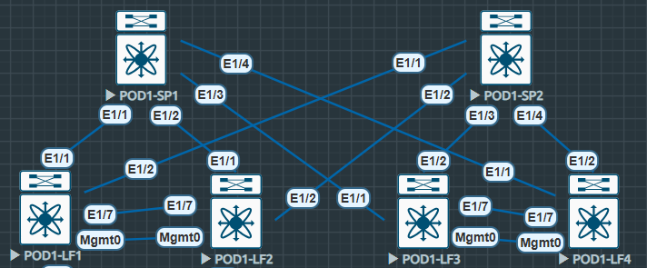
The diagram below shows our Spine and Leaf topology, however this time we can see the connected endpoints.

In this section we will be looking at communication between endpoints within the VLAN100 L2VNI we have configured previously.
The endpoints are configured on EP1 and EP2 as follows.
EP1 | SVI 100 | IP: 192.168.100.1/24
EP2 | SVI 100 | IP: 192.168.100.2/24
Initially we can run a ping from EP1 and confirm connectivity over our L2VNI.
#EP1
EP1#sh ip int br | i Vlan100
Vlan100                192.168.100.1   YES NVRAM  up                    up

EP1#ping 192.168.100.2
Type escape sequence to abort.
Sending 5, 100-byte ICMP Echos to 192.168.100.2, timeout is 2 seconds:
!!!!!
Success rate is 100 percent (5/5), round-trip min/avg/max = 10/12/19 ms
#EP2
EP2#sh ip int br | i Vlan100
Vlan100 192.168.100.2 YES NVRAM up up
EP2#ping 192.168.100.1
Type escape sequence to abort.
Sending 5, 100-byte ICMP Echos to 192.168.100.1, timeout is 2 seconds:
!!!!!
Success rate is 100 percent (5/5), round-trip min/avg/max = 9/14/22 msThe pings tells us it’s working however we want to see more from our Leaf nodes.
Initially we can check the status of our NVE Peers the Peer-IP is the other shared VTEP configured on LF3 and LF4.
POD1-LF1# sh nve peers
Interface Peer-IP          State LearnType Uptime   Router-Mac
--------- ---------------  ----- --------- -------- -----------------
nve1      100.200.255.100  Up    CP        04:48:47 n/a
Next the show nve vni command gives us the VNI, Multicast-group, State, Mode (Control Plane) and Type (L2) as well the BD which is our VLAN ID 100. We can also see the SA flag for suppress-arp. Note the VNI matchs the vn-segment used throughout the configuration.
#POD1-LF1
POD1-LF1# show nve vni
Codes: CP - Control Plane        DP - Data Plane
       UC - Unconfigured         SA - Suppress ARP
       SU - Suppress Unknown Unicast
       Xconn - Crossconnect
       MS-IR - Multisite Ingress Replication

Interface VNI      Multicast-group   State Mode Type [BD/VRF]      Flags
--------- -------- ----------------- ----- ---- ------------------ -----
nve1      160100   228.0.100.1       Up    CP   L2 [100]           SA
nve1      160200   229.0.200.1       Up    CP   L2 [200]           SA
Now we can check the l2forwarder MACs, note the MAC address we see on LF1 is the MAC for SVI100 on EP2 which is directly connected to LF3 and LF4s VPC.
This is the opposite to LF3 where we can see the nve-peer1 MAC as the MAC address of SVI100 on EP1 connected directly to LF1 and LF2s VPC.
#EP2
EP2#sh int vlan 100
Vlan100 is up, line protocol is up
  Hardware is Ethernet SVI, address is 5000.0007.8064 (bia 5000.0007.8064)
  Internet address is 192.168.100.2/24
#POD1-LF1
POD1-LF1# show system internal l2fwder mac | i nve-peer
* 100 5000.0007.8064 static - F F nve-peer1 100.200.255.100 Finally we can look at the BGP L2VPN EVPN RIB. I have looked specifically at the 160100 vni-id for VLAN100.
We can see in the output below the L2VNI RD listed. Also more specifically the MACs and the IP addresses. Listed as Next-hops are the Lo100 shared VTEP address.
#POD1-LF1
POD1-LF1# show bgp l2vpn evpn vni-id 160100
BGP routing table information for VRF default, address family L2VPN EVPN
BGP table version is 1217, Local Router ID is 10.222.222.2
Status: s-suppressed, x-deleted, S-stale, d-dampened, h-history, *-valid, >-best
Path type: i-internal, e-external, c-confed, l-local, a-aggregate, r-redist, I-i
njected
Origin codes: i - IGP, e - EGP, ? - incomplete, | - multipath, & - backup, 2 - b
est2

   Network            Next Hop            Metric     LocPrf     Weight Path
Route Distinguisher: 10.222.222.2:32867    (L2VNI 160100)
*>l[2]:[0]:[0]:[48]:[5000.0006.8064]:[0]:[0.0.0.0]/216
                      100.200.255.1                     100      32768 i
* i[2]:[0]:[0]:[48]:[5000.0007.8064]:[0]:[0.0.0.0]/216
                      100.200.255.100                   100          0 i
*>i                   100.200.255.100                   100          0 i
*>l[2]:[0]:[0]:[48]:[5000.0006.8064]:[32]:[192.168.100.1]/272
                      100.200.255.1                     100      32768 i
*>i[2]:[0]:[0]:[48]:[5000.0007.8064]:[32]:[192.168.100.2]/248
                      100.200.255.100                   100          0 i
* i                   100.200.255.100                   100          0 i
Some additional explanation of the l2vpn evpn route
- 2 = Type-2 Route (MAC / IP Advertisement)
- 48 = MAC Address Length
- 32 = IP Address is /32
- 272 = Total Length of entry
- MAC
- IP
[2]:[0]:[0]:[48]:[5000.0006.8064]:[32]:[192.168.100.1]/272
We can also specifically check our L2VNI ID, RD and RT to confirm what we’re seeing in the table is correct.
POD1-LF1# show bgp evi 160100
-----------------------------------------------
  L2VNI ID                     : 160100 (evi_160100)
  RD                           : 10.222.222.2:32867
  Prefixes (local/total)       : 0/4
  Created                      : Jun 25 09:35:51.220181
  Last Oper Up/Down            : Jun 25 09:35:51.220351 / never
  Enabled                      : Yes
  Active Export RT list        :
        65001:160100
  Active Import RT list        :
        65001:160100
VXLAN L3VNI Configuration
Now we have two L2VNIs configured, we can communicate within each of the L2VNIs however we cannot communicates between L2VNIs.
Intra-L2VNI is OK
Inter-L2VNI is DOWN
To fix this we need to utilise an L3VNI, this enables us to route between separate L2VNIs and their subnets.
Again no configuration required on the Spines. First we conmfigure our vrf with a unique vni, our RD, auto RT again and the ipv4 address-family (At this point we’re communicating at IP, hence the additions of address-family ipv4). The both section of the route-targets references both the import and export RT.
#POD1-LF1
vrf context TENANT-1
  vni 200000
  rd auto
  address-family ipv4 unicast
    route-target both auto
    route-target both auto evpn
Next we add our SVIs into our VRF and create an L3VNI SVI interface. The VNI configured under VLAN1000 should be the same as configured under the VRF context.
#POD1-LF1
vlan 1000
 name L3VNI
 vn-segment 200000

interface vlan 100
 vrf member TENANT-1

interface vlan 200
 vrf member TENANT-1

interface vlan 1000
 description L3VNI-T1
 vrf member TENANT-1
 ip forward
 no shut
Now we add our L3VNI as a member VNI under our NVE interface. Notice how we utilise the associate-vrf command, this is used to identify and process VNIs that are associated with a VRF. This is the part that links our L2VNIs with our L3VNI. Also note we don’t need to specify the VRF here as we’ve already specified it under our SVI.
interface nve1
  member vni 200000 associate-vrf
Then finally we create our vrf TENANT-1 within BGP to ensure our addressing is advertised. In this instance i’ve used network statements however normal BGP rules apply, we could redistribute the connected anycast gateway subnets.
#POD1-LF1
router bgp 65001
  vrf TENANT-1
    log-neighbor-changes
    address-family ipv4 unicast
      network 10.10.10.0/24
      network 192.168.100.0/24
Now we’ve completed the configuration for our L3VNI we can carry out our confirmation exercises.
VXLAN L3VNI Confirmation
As before we can test initially by pinging between the IP addresses configured on different L2VNIs.
We’ll be pinging from EP1 VLAN 100 to EP2 VLAN 200
#EP1
EP1#sh ip int br | i Vlan100
Vlan100                192.168.100.1   YES NVRAM  up                    up

EP1#ping 10.10.10.2 source 192.168.100.1
Type escape sequence to abort.
Sending 5, 100-byte ICMP Echos to 10.10.10.2, timeout is 2 seconds:
Packet sent with a source address of 192.168.100.1
!!!!!
Success rate is 100 percent (5/5), round-trip min/avg/max = 18/21/33 ms
#EP2
EP2#sh ip int br | i Vlan200
Vlan200 10.10.10.2 YES NVRAM up up
EP2#ping 192.168.100.1 source 10.10.10.2
Type escape sequence to abort.
Sending 5, 100-byte ICMP Echos to 192.168.100.1, timeout is 2 seconds:
Packet sent with a source address of 10.10.10.2
!!!!!
Success rate is 100 percent (5/5), round-trip min/avg/max = 14/19/33 msNow we can confirm the routing table on the Leaf nodes. we see on each of the routes TENANT-1, the encap: VXLAN and also the 100.200.255.100%default this basically mean next-hop is the VTEP however you’ll need to the default global route table for that one %. We can also see the segid: 200000 which is our configured VNI.
From LF1 we can see the EP2 VLAN200 address
From LF3 we can see the EP1 VLAN100 address
POD1-LF1# sh ip route 10.10.10.2 vrf TENANT-1
IP Route Table for VRF "TENANT-1"
'*' denotes best ucast next-hop
'**' denotes best mcast next-hop
'[x/y]' denotes [preference/metric]
'%<string>' in via output denotes VRF <string>

10.10.10.2/32, ubest/mbest: 1/0
    *via 100.200.255.100%default, [200/0], 00:07:55, bgp-65001, internal, tag 65
001 (evpn) segid: 200000 tunnelid: 0x64c8ff64 encap: VXLAN
POD1-LF3# sh ip route 192.168.100.1 vrf TENANT-1
IP Route Table for VRF "TENANT-1"
'*' denotes best ucast next-hop
'**' denotes best mcast next-hop
'[x/y]' denotes [preference/metric]
'%<string>' in via output denotes VRF <string>
192.168.100.1/32, ubest/mbest: 1/0
*via 100.200.255.1%default, [200/0], 00:07:36, bgp-65001, internal, tag 6500
1 (evpn) segid: 200000 tunnelid: 0x64c8ff01 encap: VXLANNow we can also see within the BGP L2VPN EVPN RIB the type-5 route for IP Prefix Routes, RD and L3VNI.
POD1-LF3# show bgp l2vpn evpn vni-id 200000
BGP routing table information for VRF default, address family L2VPN EVPN
BGP table version is 612, Local Router ID is 10.222.222.3
Status: s-suppressed, x-deleted, S-stale, d-dampened, h-history, *-valid, >-best
Path type: i-internal, e-external, c-confed, l-local, a-aggregate, r-redist, I-i
njected
Origin codes: i - IGP, e - EGP, ? - incomplete, | - multipath, & - backup, 2 - b
est2

   Network            Next Hop            Metric     LocPrf     Weight Path
Route Distinguisher: 10.222.222.3:3    (L3VNI 200000)
*>l[2]:[0]:[0]:[48]:[5000.0002.0007]:[0]:[0.0.0.0]/216
                      100.200.255.100                   100      32768 i
*>l[5]:[0]:[0]:[24]:[10.10.10.0]/224
                      100.200.255.5                     100      32768 i
*>l[5]:[0]:[0]:[24]:[192.168.100.0]/224
                      100.200.255.5                     100      32768 i
POD1-LF1# show bgp l2vpn evpn vni-id 200000
BGP routing table information for VRF default, address family L2VPN EVPN
BGP table version is 1519, Local Router ID is 10.222.222.2
Status: s-suppressed, x-deleted, S-stale, d-dampened, h-history, *-valid, >-best
Path type: i-internal, e-external, c-confed, l-local, a-aggregate, r-redist, I-i
njected
Origin codes: i - IGP, e - EGP, ? - incomplete, | - multipath, & - backup, 2 - b
est2
Network Next Hop Metric LocPrf Weight Path
Route Distinguisher: 10.222.222.2:4 (L3VNI 200000)
*>l[2]:[0]:[0]:[48]:[5000.0005.0007]:[0]:[0.0.0.0]/216
100.200.255.1 100 32768 i
*>l[5]:[0]:[0]:[24]:[10.10.10.0]/224
100.200.255.3 100 32768 i
*>l[5]:[0]:[0]:[24]:[192.168.100.0]/224
100.200.255.3 100 32768 iAgain like with our L2VNIs we can confirm the L3VNI ID, RTs, and RDs
POD1-LF1# show bgp evi 200000
-----------------------------------------------
  L3VNI ID                     : 200000 (evi_200000)
  RD                           : 10.222.222.2:4
  Prefixes (local/total)       : 0/3
  Created                      : Jun 25 09:35:49.052792
  Last Oper Up/Down            : Jun 25 15:59:05.159339 / Jun 25 15:59:04.938427
  Enabled                      : Yes
  Associated vrf               : TENANT-1

Address-family IPv4 Unicast
  Active Export RT list        :
        65001:200000
  Active Import RT list        :
        65001:200000
  Active EVPN Export RT list   :
        65001:200000
  Active EVPN Import RT list   :
        65001:200000
  Active MVPN Export RT list   :
        65001:200000
  Active MVPN Import RT list   :
        65001:200000

Address-family IPv6 Unicast
  Active Export RT list        :
        65001:200000
  Active Import RT list        :
        65001:200000
  Active EVPN Export RT list   :
        65001:200000
  Active EVPN Import RT list   :
        65001:200000
  Active MVPN Export RT list   :
        65001:200000
  Active MVPN Import RT list   :
        65001:200000
We can also reconfirm our nve vni and see that our Type L3 is UP for TENANT-1
POD1-LF1# sh nve vni
Codes: CP - Control Plane        DP - Data Plane
       UC - Unconfigured         SA - Suppress ARP
       SU - Suppress Unknown Unicast
       Xconn - Crossconnect
       MS-IR - Multisite Ingress Replication

Interface VNI      Multicast-group   State Mode Type [BD/VRF]      Flags
--------- -------- ----------------- ----- ---- ------------------ -----
nve1      160100   228.0.100.1       Up    CP   L2 [100]           SA
nve1      160200   229.0.200.1       Up    CP   L2 [200]           SA
nve1      200000   n/a               Up    CP   L3 [TENANT-1]
That’s all for now…
